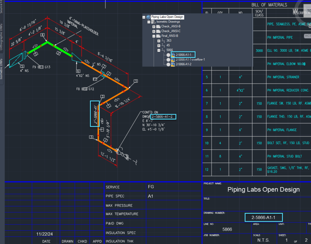
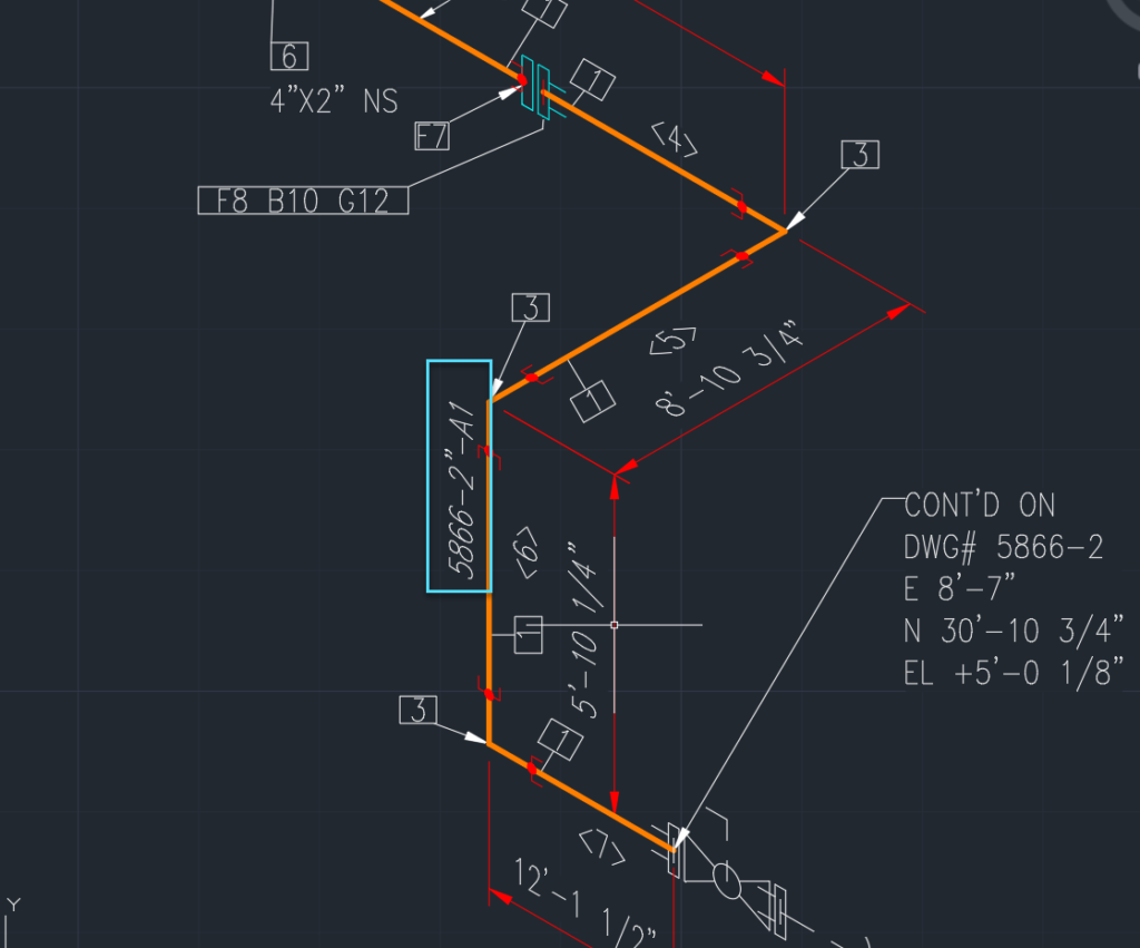
One item people often want to configure in Plant 3D is how the line numbers are displayed. Over the years, the tools for doing this have changed even though the underlying xml formatting has not. Here’s a screenshot showing the default isometric that has the P3DLineGroup Tag value (5866) followed by the size (2″) and then the spec “A1.” Our goal will be to change the line number so that it display size-number-spec.
Typically this line number format will need to show up in 3 places.
- Along the pipe line.
- In continuations.
- As the filename.
When complete, you will be able to configure your isometrics to show line numbers that look like this:
Below is a screen shot of the default setup.
We used to have to go through PLANDEFINECALCPROPERTIES to set this up, but now we can work directly in Project setup.
Summary of Workflow
- Setup a calculated property for your line suffix.
- Set up calculated property (IsoLineNumber) for your full line tag.
- Configure Acquisition properties for nominal size and nominal spec.
- Configure the File name format.
- Configure the annotation that dislays on the line.
- Configure the drawing name format.
LIne Suffix
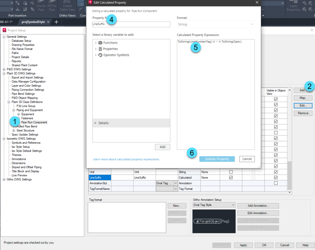
Create the Line Suffix property on the Plant 3D Class Definitions > Piping and Equipment > Pipe Run Component (1) & (2) class. Create it as a calculated property. Name it LineSuffix (4), and then for the expression use (5) ToString(LineNumberTag) || ‘-‘ || ToString(Spec). If you wanted to include other properties, you can. For properties from the line group (like Service), you would need to set that up as an acquisition property on Pipe Run Component first, before it is available here. The Line Suffix will be used in the drawing area along the pipe line.
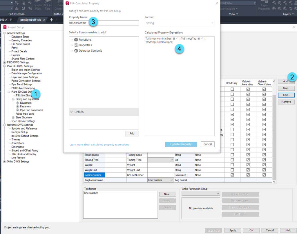
Set up the Iso LIne Number property
The IsoLineNumber property will be used for the connected drawings, title block, and file name. Create the IsoLineNumber property on the P3DLineGroup (1), (2), and (3). Then setup the expression to equal what you want to see in the connected drawings area, title block and file name. Similar to above you can add additional properties from the line group. In this case, since you’re working with the line group, you would not need additional acquisition properties.
ToString(NominalSize) || ‘-‘ || ToString(Tag) || ‘-‘ || ToString(NominalSpec)
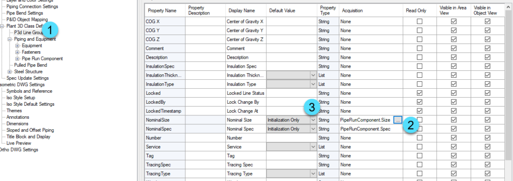
Configure Nominal Sizes
To avoid having to manually fill out nominal size and nominal spec, you can use an acquisition property. In the P3DLineGroup (1), add an acquisition for the Nominal Size to come from the PipeRunComponent.Size and for the Nominal Spec to come from the PipeRunComponent.Spec (2). Then set the Default Value to be Initialization Only (3).
When a user creates a new line group by routing pipe, the size they selected will be used to populate the nominal size and spec. Of course, those value may be adjusted at a later point manually if necessary.
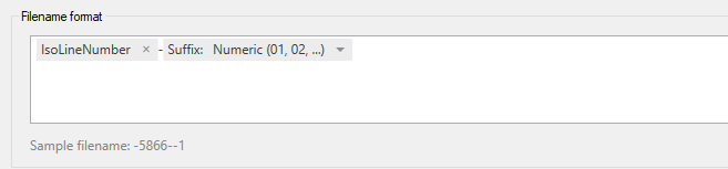
Configure the FileName Format
Most of the file name should reflect the full line number tag (Size, service, spec, number, etc). Since we created a calculated field to hold that value, you can select it in the project setup.
First, navigate to Isometric DWG Settings> Iso Style setup (1). Then remove the Line Number token (2).
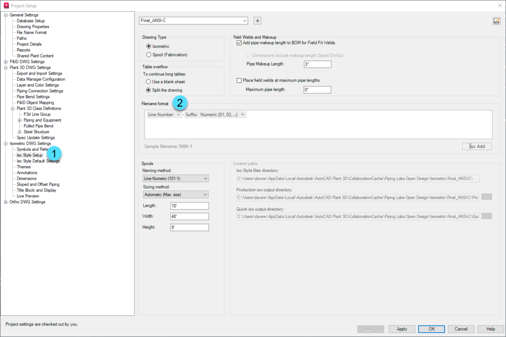
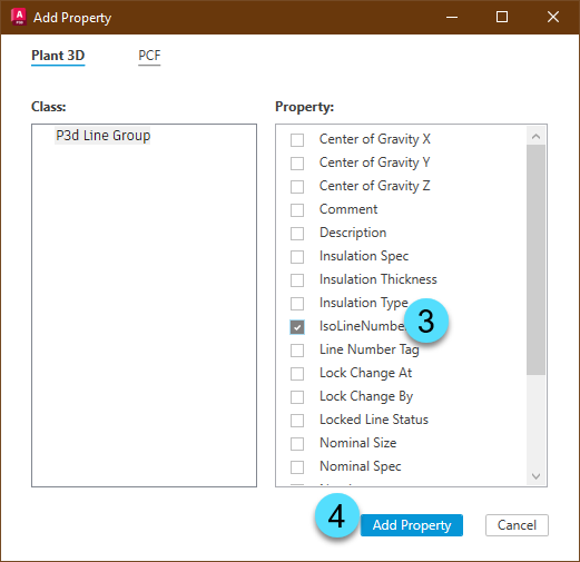
Move the cursor to the start of the filename format and click Add. From the P3D Line Group class pick IsoLineNumber (3), and then Add Property (4).
The finished filename format should look like this:
Configure the Annotation to Display Along the Line
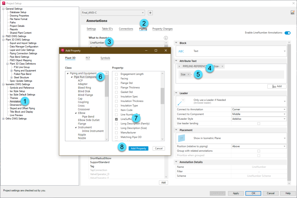
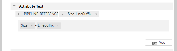
Next the annotation that will display along the line will be configured. In Isometric Drawing settings, select Annotations (1), for the style you want to modify, select Piping (2), then pick the Line Number annotation (3). You will need to expand the size dropdown (4) and then you can click in the text area (5) and click the Add button. In the Add Property dialog, pick Pipe Run Component (6) and choose LineSuffix (7), then Add Property (8).
After you have the line number configured like this, click OK to accept your changes to project setup, and close the Project Setup dialog.
Due to some weird UI behavior, you cannot change the sequence of the PIPELINE-REFERENCE location in the Attribute text, nor can we remove it from the Attribute text. You also cannot modify it in the built xml editor.
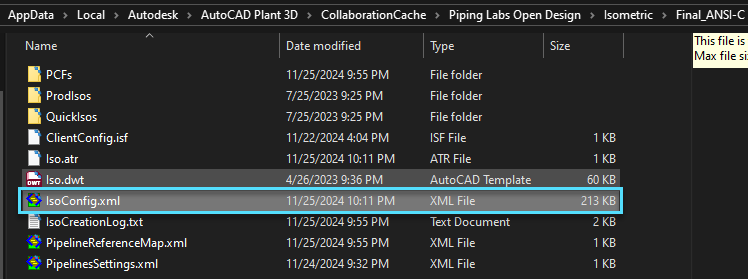
With Project Setup closed, navigate to the folder that contains the IsoConfig.xml for your style and open the xml file in an xml editor like Foxe.
In the Isoconfig, navigate down to Themes > Theme (Default) > Annotations > AnnotationSchemes > LineNumberScheme. In the Format entry at the right, modify it to only show {1}.

Why does using {1} work?
The Format entry allows you to combine the ComponentFormat {1} and the LineFormat {0}. The unfortunate part is that you can’t pull out individual fields from the other formats. You get all what is in LineFormat first, or all of the fields used in ComponentFormat first. LineFields tells us what properties will be used in LineFormat, and LineFormat tells how to order them. Similarly, ComponentFields tells us what properties will be in ComponentFormat, and ComponetFormat tells us how they will be ordered. In this case, all of our properties come from the ComponentFormat, so we are ignoring the LineFormat completely.
Save the file. If you’re project is in ACC or Vault, open project setup, check out the settings and then click OK. That process will upload the IsoConfig.xml changes to the cloud.
Configure the Drawing Name Format
While in the iso xml editor, you should configure the drawing name format. We do not have the capability of modifying this in the UI, so the change needs to be made in the xml.
The format generally matches the filename format, so you can use that as the basis.
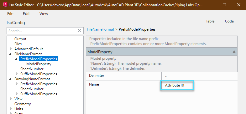
First, navigate to FileNameFormat > PrefixModelProperties and note the name of the ModelProperty being used. In this case, it’s Attribute10.
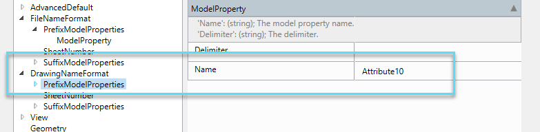
Next, navigate to DrawingNameFormat > PrefixModelProperties and enter the same value in the Name property.
Why does Attribute10 work?
In the background, when we added the IsoLineNumber to the Filename, the application adds an entry into the Iso.atr file with the attribute and the property. In this instance it adds a line number ATTRIBUTES that says ATTRIBUTE10 P3dLineGroup.IsoLineNumber.
Click File > Save, and then exit.
Test the Configuration
At this point, the style should be properly configured. Run a test isometric, and verify that you see all the changes properly applied.
Test the Configuration
Because of how the acquisitions are setup on the line group, you will need to route a new line to verify that the nominal size and spec are populated. When the line is routed, run a production isometric to test the configuration.
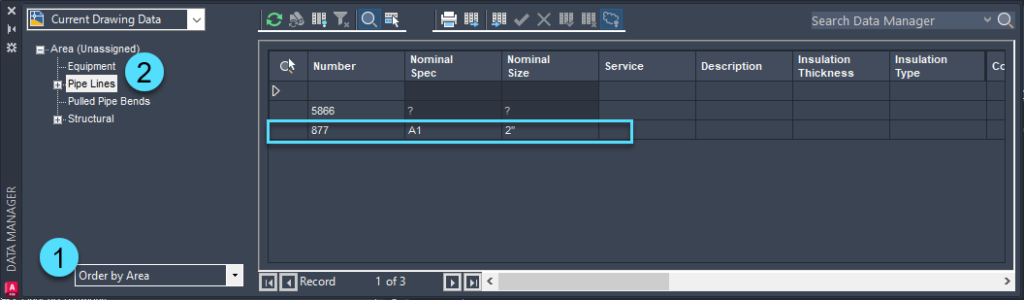
Open the Data Manager, switch to Order by Area (1), and then click Pipe Lines (2). Verify that the Nominal Size and Spec were filled out.